
First boards nearly completed: digital board and PSU. Next will be the DMUX board so I can start testing the various voltages as well as the digital and digital-to-analog sections.
First boards nearly completed: digital board and PSU. Next will be the DMUX board so I can start testing the various voltages as well as the digital and digital-to-analog sections.

First batch of parts arrived. Board and components for the PSU and Digital boards, SMD resistors and capacitors, and most components for the DMUX board. Also, Curtis chips were ordered from Alfa and are on their way! Connectors and several random items, such as the alphanumeric display, were already received.
At this point the DMUX board should be under production; however the issue with different libraries for the SMD ICs made me wait until the components arrive prior to sending the board for production. In the mean time, I decided to make a few modifications: now, Ground, +15V/-15V, +7.5V/-7.5V and Noise are all sent to the Voice Boards thru the same connector, making wiring cleaner. In the original design these are divided in two connectors. Also, connectors between different boards now have matching pinouts. For some reason, in the original Memorymoog, pins, say, 1 to 5 in one board would connect to pins 3, 2, 5, 1 and 4 in the other, making for pretty confusing interconnections. Now, pin 1 in one board goes to pin 1 on the other and so on. Oh, and rounded the corners in the boards!
Made an effort to reduce the number of vias in the boards by routing the traces as efficiently as I could. In some baords I could eliminate some 50 vias or more.

Ordered most of the parts by now, and sent the Power Supply and Digital boards for production. Will wait until the ICs I ordered arrive because I am not sure which of the SMD IC footprints I should use; Kicad has updated the libraries from version 4 to 5 and now I am not sure which is the footprint that better fits the actual component.

Changing the footprint will require some rework on the traces that run under the ICs because the new footprint is narrower, leaving less room for the traces. The plan is to print both layouts on paper soon as I receive the ICs and then place the actual component over the printout to verify which is the best for hand soldering.
As the Digital Board uses only thru-hole components, I decided to send this board to production first. Will place pictures soon as I receive them!
After some consideration, I removed the ground plane initally placed in 100% of the bottom layer of the board. Reason for that was the constatation that for this board, pouring a large ground was producing lots of “dead end” ground areas, which may be even worse than no ground plan at all; one GND and one Earth planes were left for the S&H section only. Ideally, the board would have 4 layers, one of them dedicated for ground only, with no traces. However, there is no need for that. Two layers should do the job nicely. Also, decided to change a few ICs from SMD to DIP format should I have to replace a chip. Anyway, this board is pretty much ready for production. Already ordering the components for this board! After the power supply, this should be the next board to get built.

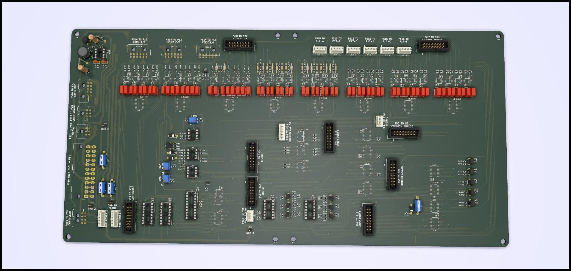
Just found out I had a mixup with my Kicad libraries. I was founding it odd that only the Pinhead connectors were being rendered in the 3D view. Turns out that when upgrading from Kicad 4 to 5, the libraries have to be deleted and the new libraries have to be added – a manual process. As a result, now most components are rendered in the 3D view, such as in the Common Analog board shown here (side by side with the original Common Analog as found in the Memorymoog):


Not much change from the original. The first board I designed; tried to keep the component distribution more or less the same as the original. Had to guess the size of the original board by measuring the drawing using the pins in the CPU as a “ruler”… In this redesign, all ICs now have decoupling capacitors, all assembled close to the supply traces, and a ground plane is added. Power connector is a Molex Microfit, and all IDCs were changed from the DIP format used in the original for what I believe is a more reliable option, similar to the IDE connectors found in older PCs. Using 27C32 EPROMS now (slight different pinout from the hard to find 2532 in the original). The 27C32 uses way less power, 26mW (compared to the 550mW in the original 2532).

3D rendering of the redesigned DMUX board. Power connector is now a standard ATX, as used in PCs. Power supply is supposed to deliver some 70W in total (I think… do not have the exact current drawn by the synth figured yet. Use of modern components should reduce this amount). The ATX (Minifit) and Microfit connectors should be more than enough to handle these currents. Next development is to replace the six vertical connectors to the voice cards at the right center with horizontal ones, to reduce strain at the connectors because this board will sit under the Common Analog board. Reduced headroom between this board and Common Analog may bend the wires out of these connectors, so mounting them horizontally is a better approach.
3D rendering of the current design for the voice cards. Changed trimpots for VCO 1 to see the difference in layout before deciding in one type over the other. Relocated power connector further inside the board so the cables would not interfere with the board to the left. Still considering moving all other trimpots (total of 6 trimpots for filter, VCA and modulation calibration) to the lower edge of the board so they may be accessible without even removing the cards in the top. Most pinhead connectors shown are actually resistor networks, but I will probably just use 100K 0.1% metal film resistors instead.


Think the logical starting point is the power supply. This will be needed for testing and debugging all other boards, so started it is! Just ordered the transformer, similar to the one pictured above; fan will be a standard PC cooling fan, much quieter both accusticaly and electrically than the original fan. I am rethinking my idea of making the trimpots accessible from the back of the instrument; power supply calibration should not be something that is required frequently, so I may rotate the trimpots from their current position to make them accessible from the inside of the instrument only.
