In the late 90s I used to own a Memorymoog synthesizer – which I guarantee, were extremely rare in Brazil – and probably even more difficult to find now, after 18 years. This synthesizer was a beast – in every aspect: sheer size, weight, sound, heat generation, everything is big, brutal.
Using early 80s technology, many of its components became obsolete, no longer in production, and harder and harder to source. Should one of the Curtis ICs fail, finding a replacement would be next to impossible. This is the main reason why I ended up selling the synthesizer, before it died in my arms.
Good news is: recently these rare Curtis chips were re-released by more than one manufacturer, at affordable prices. Recreating some of the original instrument electronic boards was no longer impossible, so I started to study the Memorymoog schematics to figure if it would be possible to clone some of the circuits in modular format to include these in my – currently stalled – home made modular synthesizer. Eventually I figured that, yes, it is possible to recreate all of the boards, eliminating some problems that plagued the machine in the process, such as poor choice for the connectors conducting various signals and voltages inside the instrument. Cloning the whole thing would just be a matter of patiente and careful work!
Work has already strarted in this project. The plan is:
- Design all the printed circuit boards, using SMD components whenever possible.
- Recreate the external case for the instrument. Will work on the control panel boards only after the case is ready
- Source all the components
- Check the boards versus actual components
- Have the boards made
- Stuff them with some, I don’t know, 4000 or so components
- Connect everything, test, debug
- ??
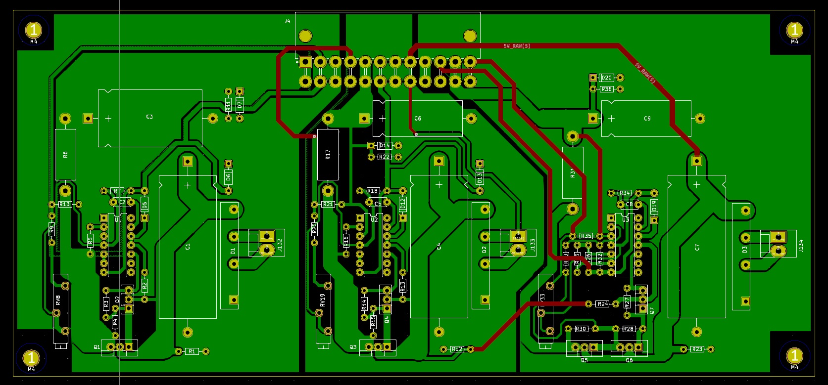
This is a screenshot of my version of the Memorymoog voice board. In total, the Memorymoog has 6 identical boards. In the original instrument, the boards are assembled in 2 stacks of 3 boards, so reaching for the calibration trimpots is a real pain. The new version is much more compact, so I will use 3 stacks of 2 boards, making room for the Contour/Glide board to be mounted under the voice cards. Also, the VCO calibration trimmers are mounted in the rear section of the card so these will be accessible thru a removable cover in the back of the instrument. Calibration can be performed without opening the case.
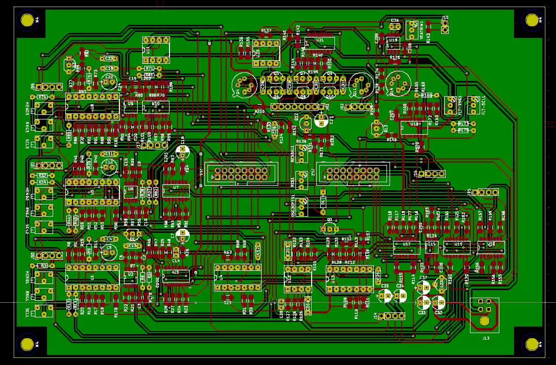
The voice card connectors in the original are pretty problematic. In the unit I had, merely touching those connectors during a calibration attempt was enough to make the pitch drift. In the new version I am using Molex NanoFit connectors, which, I hope, are be more reliable. Also, all other connectors will be latched MTA-100. The use of ground plane in the board is another addition.
Something that I am still not entirely sure is the VCAs used for the Resonance (called Emphasis in the Memorymoog) and contoured voice amplitude. The Memorymoog uses two CA3080s transconductance operation amplifiers; as I have just a copule of those and a whole lot of LM13700s in SMD format, well, 13700 it is. I may end up creating two versions of this board and compare the sound of both before deciding which way to go: use my stash of LM13700s, or try and source a dozen of 3080s.
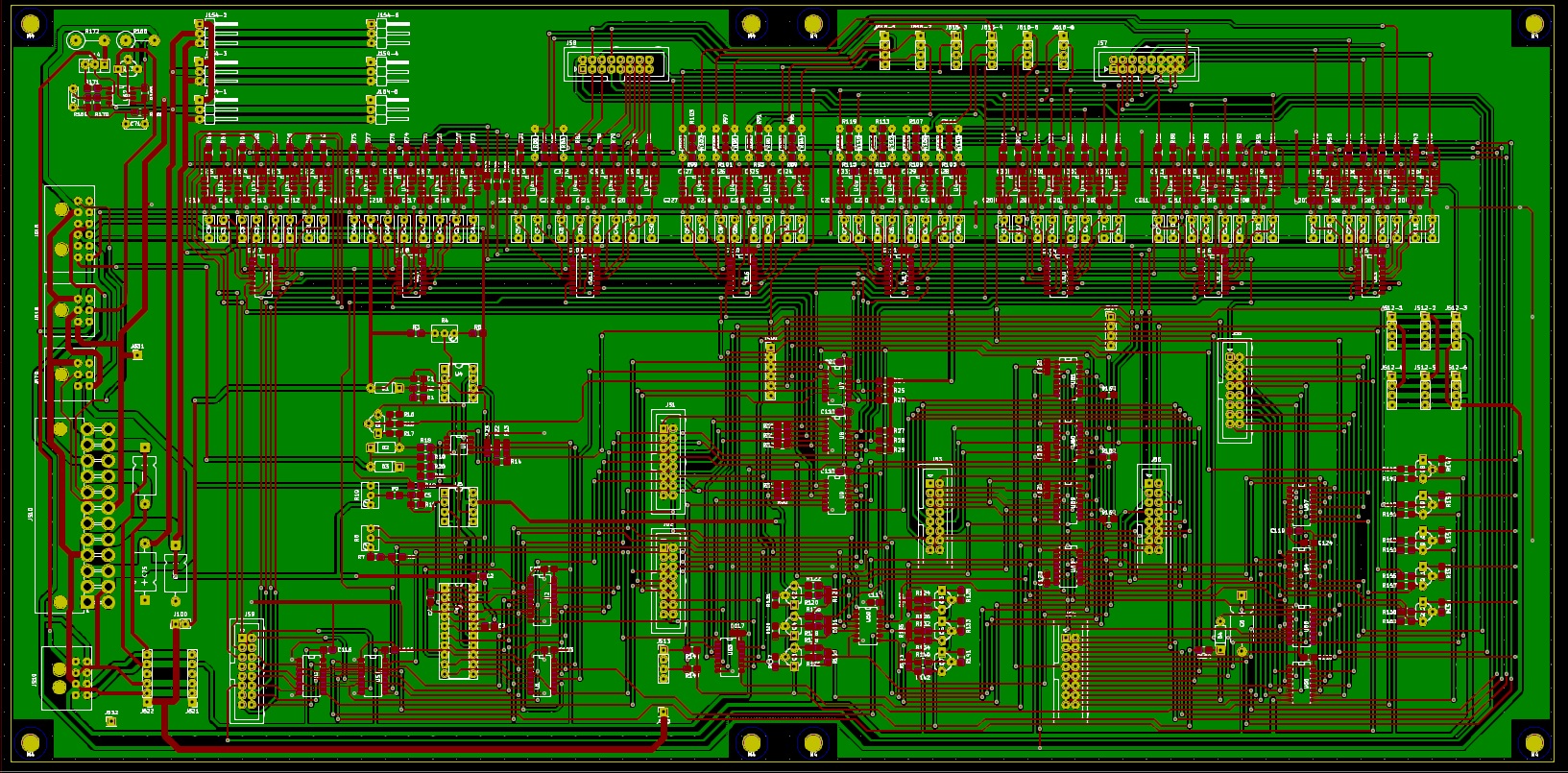
The Common Analog Board, surprisingly, ended up much less dense than I initially imagined. This board did benefit a lot from the use of SMD components, the original is crammed with components. Since it is mounted on the top of the Demux board, I chose not to change the board size because in doing so I would have to also change the DMUX board dimensions so the mounting drills would match. Maybe in a future revision?
The noise generator chip, a MM 5837 chip (replaced by the MM 5437 in a revision) is pretty hard to find these days. Fortunatley our friends at http://www.electridruid.net created a modern version using a 12F675 PIC. It is not a direct replacement, however; some small changes from the original circuit are required. For example, the original chip uses +15V, and the PIC cannot see more than 5.5V. A small voltage regulator was included in the board; it was easier than rerouting the power to add +5V to the board. As well, some components will have to be changed to accomodate for the different signal amplitude generated by the PIC. Nothing that cannot be solved with some prototyping and a few resistors changed. Easy, I hope!
The DMUX board had a number of issues in the original. I chose to maintain a few ICs in the original DIP package; all power connectors are also latched, the Power Supply connector was replaced with the same type of connector found in standard ATX PC power supplies, all capacitors for the Sample and Hold CVs are metallized polypropylene, a large ground plane was placed on the board, and some of the connections were rerouted. For example, there were some 5 wires soldered directly on the board that connected to the Common Analog board; those were rerouted to a connector. Also, the Resonance signal was rerouted to the voice boards making the wiring a bit cleaner. I can probably modify the connectors that send +/-15V to the voice cards, not entirely sure if the connectors I chose are the best option. This board cannot be too high because it is mounted under the Digital/Common Analog board so I am somewhat limited in the connector types that can be used. Initially I thought about using Phoenix connectorsand eventually switched to MTA-100 style connectors, mounted horizontally to reduce the required height. However, this is still open to modification.
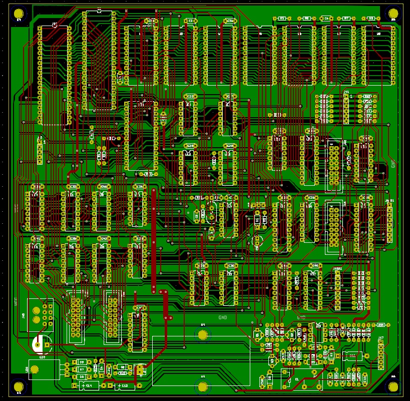
The Digital Board was the first board I created. My inital idea was to reproduce the boards exactly as the originals, so for this board I created a version with no SMD components. The original 2532 EPROMS were hard to find, and I happened to have a small mountain of 2732 EPROMS at hand, so I used those instead. Pinout is slightly different, but other than that I expect no issues.
I should had modified the address logic and used one single 27C128 instead of 4x 2732, and a single SRAM chip. This would simplify the board design a lot, as well as using SMD components in the analog section. Maybe in a future revision? Also, not sure why I left the 40-pin expansion connector in my board. It will be hard enough to actually make this prototype work, let alone add a sequencer to it!
The power supply is basically the same as the original, only the discrete bridge rectificator was replaced with a power bridge, and the connector is now the same as used in ATX power supplies. Voltage adjustment trimpots face the rear end of the card and, just as for the voice trimpots, can be adjusted without opening the instrument.
Now, still need to figure what are the specs for the Memorymoog transformer so I can order one. Have to investigate if it is possible to have a toroidal transformer made, but for that I need to know the exact voltage and current outputs of the original. Too much voltage will generate more heat from the transistors, and not enough current will lead to all sorts of unpredictable problems.
If this whole thing actually works, I may try to get a Heinz Weierhorst Memorymoog switching power supplies. I have seen good comments about those!
As of today, I still did not commited the boards to production because first I want to have all the components for each board to avoid surprises, such as finding out that a given capacitor is actually larger than the room I had for it, or that a terminal needs a drill diameter larger than anticipated. Done that, and it is frustrating!
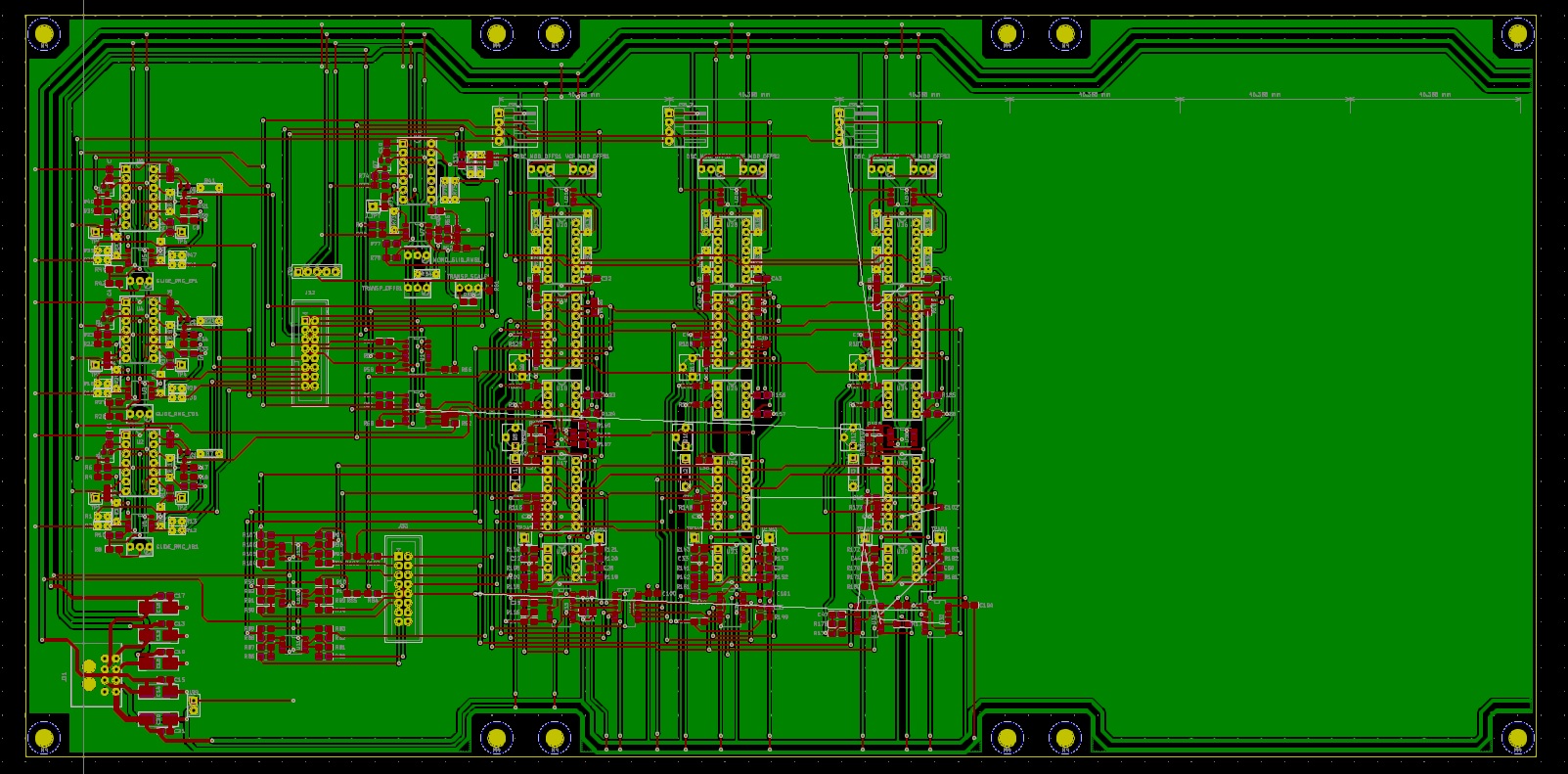
The Contour + Glide board is a work in progress, I am some 70% done. As the remaining envelope generators are a matter of copying, pasting and adjusting, I might get id ready in a couple of days, depending on how much free time I can get.
The original board used 2 connectors to send signals to the voice cards, and for some reason the pinout between this board and the voice card does not match: pin 1 in Glide board goes to pin 3 in Voice and so on. This was changed: two signals were combined in one single connector, and now the pins match. This should improve cabling organizaion.
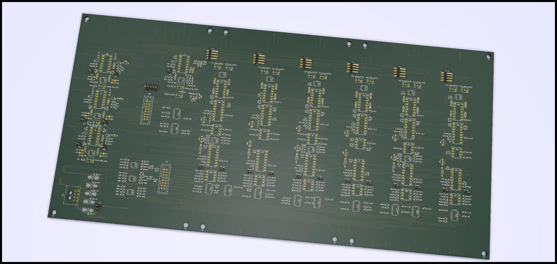
Contour/Glide board design is pretty much done. I totally forgot Kicad has a 3D visualization option… duh! Anyway, here is the board.
Just sourced a local supplier for the power supply transformer. A toroidal trafo with 110/220 primary and 18V/4A + 18V/4A + 7.5V/4A is quoted at approximately U$ 45, wich is a pretty good price range. This transformer should be more efficient and compact than the monstruous transformer used in the original Memorymoog. I just hope the 4A current is enough, still could not figure what are the specs for the origianl transformer.
